Reliable operation of the Truma S-heater

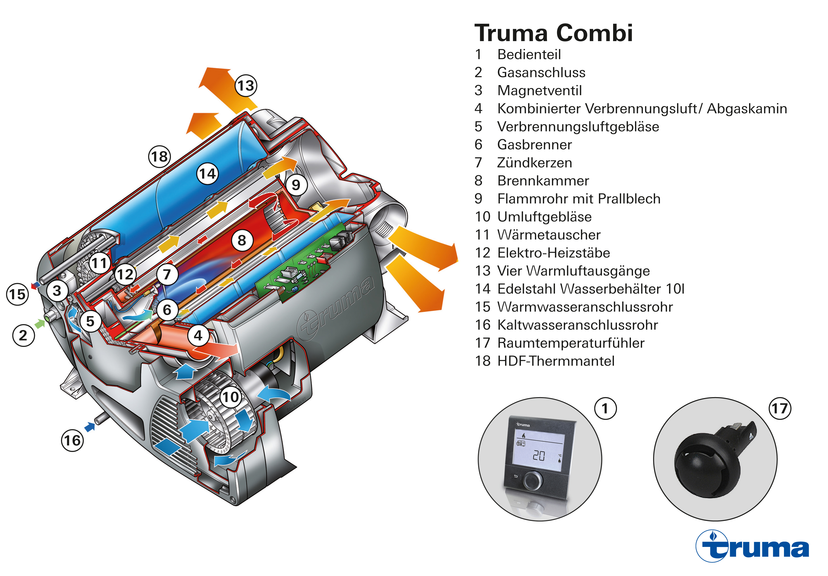
The heater is supplied with gas via a special connection (1). This is either ignited via a battery-operated auto ignition kit (2) or mechanically at the push of the button via the Piezo ignitor in the burner (3). Via the Mica window (4) it is possible to check whether the gas has ignited. External air is sucked into the heater via an inlet (5) and heated via the open flame in the burner (3). The hot air flows through the S-shaped heat exchanger (6) and escapes into the atmosphere together with the exhaust combustion gases via the exhaust pipe (7) and the roof cowl (8). Thanks to the thermo-electrical safety pilot and the fact that the system is completely closed, this process is 100% safe. The heat exchanger (6) heats the direct ambient air in the heater casing. It escapes into the living space through the lamellae of the covers and is distributed within the caravan via the fan (14) as required.

The temperature of the heater can be set steplessly and manually via the control panel knob (9), which activates the safety pilot valve (12) via the control panel rod (11). Once the required room temperature has been reached, a thermostat sensor (13) controls the gas supply to the burner and weakens it accordingly. The fan is controlled via a second control knob (10).

Schnittmodell_Heizung_Truma S 3004_DE.jpg

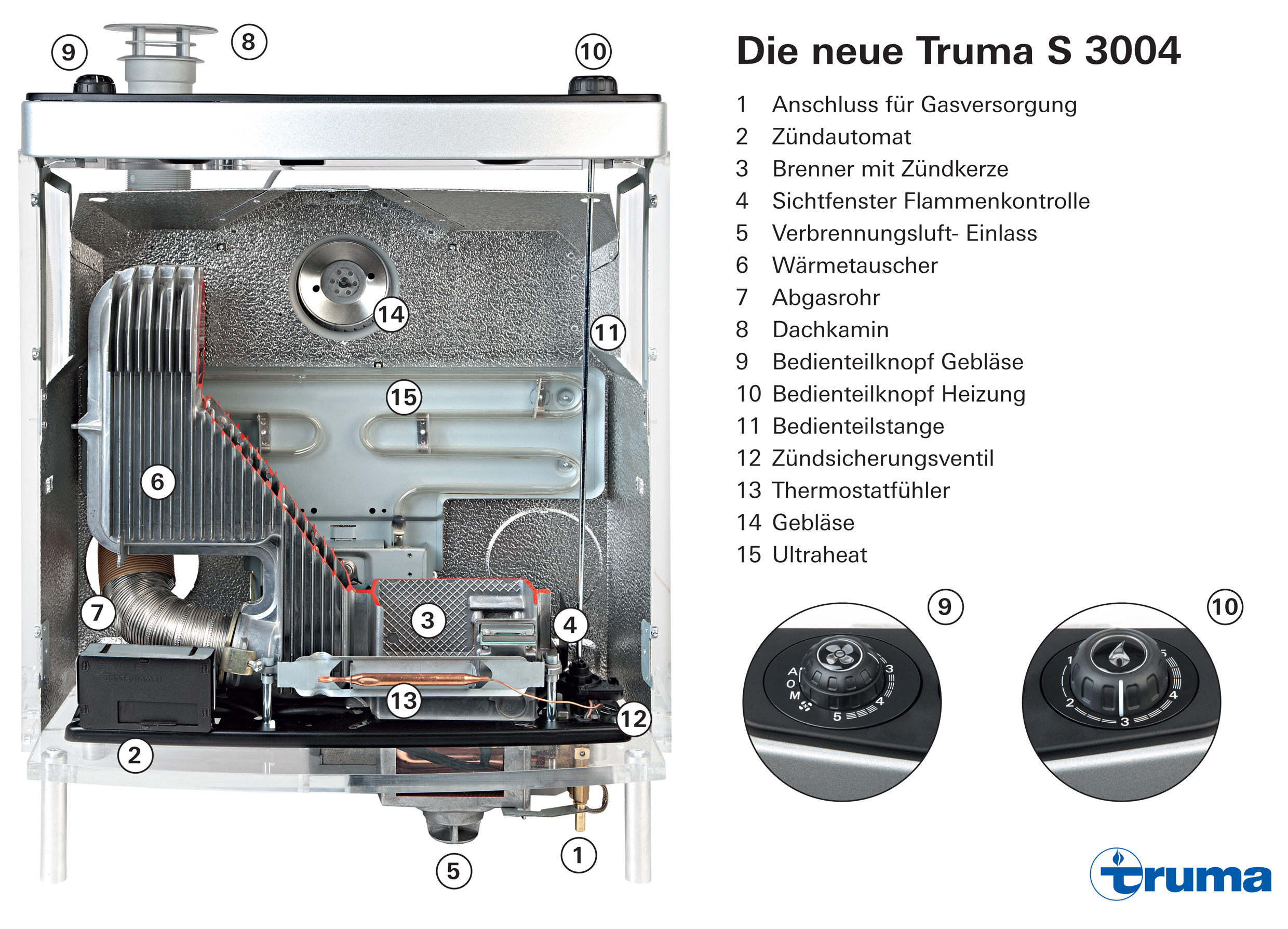
The electrical ancillary heater Ultraheat (15) is an ideal extra for all those who want to use additional electrical heating to heat up their vehicle very quickly independently of the gas system. It heats very quickly and uses the fan of the S-heater to distribute the warm air efficiently in the caravan.

Functional principle of the motorcaravan heater Truma Combi

The heater is started on the Truma Combi LCD control panel (1) and the required temperature for the heater and warm water is set. The heater is connected to the vehicle’s gas supply via the gas connection (2). The gas supply to the heater is controlled via the solenoid valve (3). The required combustion air enters the device via the external pipe of the combined combustion air/exhaust gas cowl (4) where it is transported to the gas burner (6) via the combustion air burner (5). The gas burner, which is equipped with two igniter plugs (7) and a flame rectification electrode, ignites the gas-air mix in the combustion chamber (8).

The hot exhaust gases are deflected at the end of the combustion chamber on the baffle plate of the flame tube (9) and flow back between the flame tube of the burner and the inner wall of the heat exchanger. They escape into the atmosphere via the exhaust gas cowl (4).

The circulating air fan (10) sends the air that is to be heated into the inside of the device. This air flows along the ribs of the heat exchanger (11) that, thanks to its large transfer surface, ensures optimum heat transfer. There are also additional electrical heating rods (12) with 1,800 Watt inside the heat exchanger that can be used to either heat the water and/or warm air. Then the warm air is distributed throughout the vehicle via four warm air outlets (13).

The fresh water is kept in the outer stainless steel water tank that has a volume of 10 litres (14). It is heated from here via the transfer of heat from the heat exchanger (11). Thanks to the eccentric shape of the water tank, the warm water is circulated ensuring an optimum mix and better temperature layering. The warm water connection pipe (15) connects the Truma Combi to the warm water pipes in the kitchen and bathroom. Cold water is pumped from the fresh water tank via the cold water connection pipe (16).

Schnittmodell_Truma Combi_DE.jpg

The room temperature sensor (17) fitted in the vehicle measures the air temperature in the vehicle. Also, the water temperature is measured using the internal temperature sensor. Before the required heater and water temperature is reached, the device reduces the heating output. Once the set temperature has been reached, the burner shuts down. If the set heater and water temperatures are undercut, the Truma Combi automatically restarts to heat up the air and water (winter mode). In summer mode, the warm water heater can be operated separately from the heater. The HDF thermal sleeve (18) ensures good insulation of the Truma Combi-heater.


Retrofitting the control panel Truma CP Plus – what do I need to know?

The LCD display control panel CP Plus can always be retrofitted in all Truma Combi heaters. It cannot be fitted into older heater models, e.g. the C-heater.XXX

The Combi heaters were launched by Truma in 2007 and can be recognised by the grey casing. From series start in the year 2013 the models have a black casing.

Do the electronics need to be replaced when fitting the CP Plus?

If you already have a Truma Combi heater with the appropriate software version, so only the old control panel need to be replaced with the new one (see installation instructions and user manual. Self-service (truma.com)

How can I see whether the electronics of the Combi need to be replaced?

Combi Totale(markiert)

Via the software version of the electronics. To do this, please remove the clipped on part of the electronics cover (see picture left ). You do not need tools for this.

Platine Nah(markiert)

You should now be able to see the part of the PCB to which the positive and negative cable is fitted. There is a sticker here that states the software status of the electronics (see picture on the right).

The table below shows which software status is required for which Combi model..ServiceblogTabelle CPPlus