Use Combi-Heater in winter with or without water?

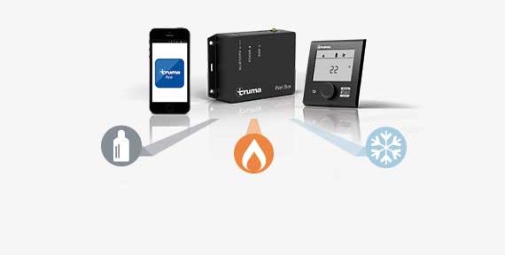
As a camper, questions arise during the winter season such as: “How do I make sure that the water in my heating system or vehicle does not freeze when I am not on site during the day?” or “Can I heat my camper or caravan without water in the boiler?

We answer both questions in this article.

If you are travelling with your vehicle in winter, you can choose between the above options to suit your needs. Both are possible, as long as the operation of the unit is adapted accordingly.

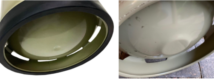
Option 1: If your motorhome or caravan is filled with fresh water, the heating should always remain active. As long as the frost monitor of the Combi, the FrostControl (FC), is exposed to an ambient temperature of >3°C, it remains closed and the water remains in the system. It is important here that the temperature is measured directly at the FC. Experience has shown that it is equally important that only the water runs out of the Combi when the FC is open. Whether the fresh water tank and all water pipes also run empty depends on the installation of the water supply by the vehicle manufacturer. This may or may not be the case. You should check this at your leisure before starting your journey.

You can set 5°C as the lowest room temperature on the heating control. If this is not sufficient to heat the FC because it has been installed further away from the Combi or a warm air pipe, a higher room temperature requirement should be set. This is possible with the CP plus from 5°C in 1°C steps. Simply approach a suitable value slowly. With the CP classic, with the two rotary knobs, level 1 also corresponds to 5°C, level 5 about 30°C. The other levels are in between. Level 2 should therefore be sufficient to keep the FC closed. Please note that such operation is only recommended during a journey. It is not a suitable means of keeping the vehicle frost-free throughout the winter. Short heating times of the heater promote the formation of condensation in the exhaust tract.

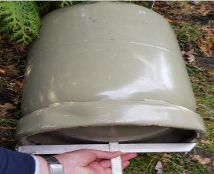
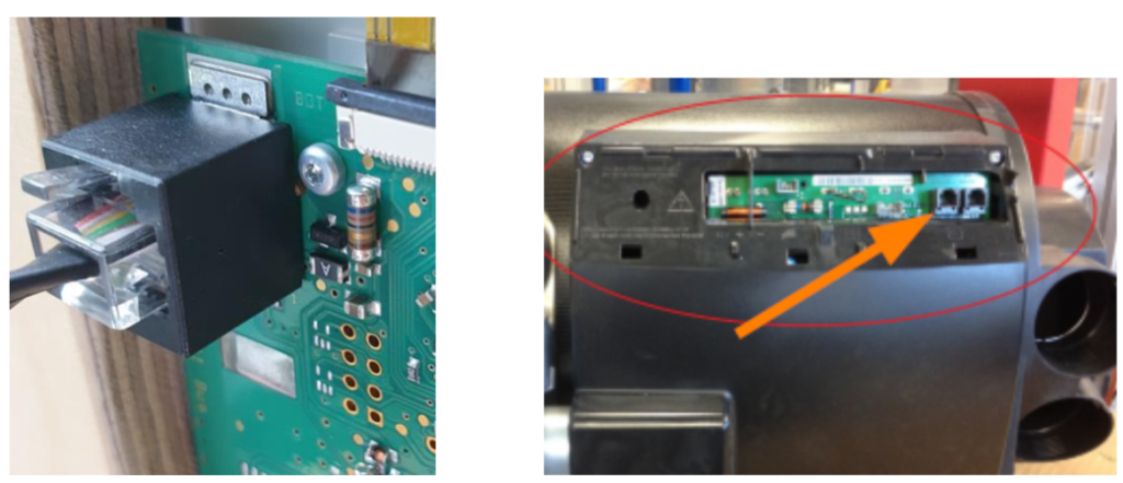
If the installation space of the FrostControl is too far away from the heater or completely unheated, a separate heating element for the FC can be purchased from our authorised dealers.

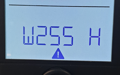
Option 2: If you are travelling without water in the system, the Combi can also be operated. The only important thing here is to set only room heating as a requirement for the Combi. The water heating programme must remain inactive. Make sure that the water tank of the Combi is correctly emptied. Residual water in the combi can get very hot very quickly. The resulting water vapour can irritate the temperature sensors of the heater and lead to a warning message “Water overtemperature detected”. For this reason, we recommend that you leave the FC open when using the vehicle in this way. This way, the water can find its way out of every corner of the fresh water supply during a winding journey. Optionally, you can help by using light compressed air or a balloon that has been put over and filled at the open water taps.

Please note: we recommend both modes of operation only on one trip. Operating the heater in one of the specified options for months should be avoided. The reason for this is that this type of use does not correspond to the intended use of an appliance for camping needs. In addition, under unfavourable conditions, condensation can collect in the exhaust pipe and disrupt the proper operation of the heating system.

With these tips, you’ll be well prepared, even when it’s cold outside. We wish you a wonderful winter holiday.

Feedback on app version 4.12.5 (iOS only)

Our app version 4.12.5 is the reaction to a bug that occurred under iOS 15.1.

The SMS function was affected, specifically the generation of an SMS (remote control/status query).

Please let us know your experience with the new app version. Is the (multiple) generation of SMS messages possible again without restrictions?

Please state in your feedback which iPhone is being used and whether the system is on the latest software version (app version 4.12.5, iNet Box FW 2.09.06).

Thank you very much for your participation.

Truma App – iOS 15.1

Hello everyone,
Thank you very much for your lively feedback.
Since the first report about a crash in the SMS generation under iOS 15.1, we have been working flat out on a solution. This was in the field test until today – and could now finally be released for you.

As usual, you can update the Truma App to version 4.12.5 via the Apple Store and the issue should now be resolved.

Regards

your Truma iNet Team

Truma iNet X System – What you always wanted to know

We would like to inform you transparently about the new system solution and offer a platform for exchange as well as answer questions for the community in the long term.

You can find the basic product information at https://www.truma.com/int/en/products/inet-x-system

There will be two different panels, a retrofit solution for you as the end customer, the Truma iNet X Panel https://www.truma.com/int/en/products/inet-x-system/truma-inet-x-panel and the Truma iNet X Pro Panel, which will be installed in new vehicles directly by the vehicle manufacturer before delivery https://www.truma.com/int/en/products/inet-x-system/truma-inet-x-pro-panel

Both systems were presented at the Caravan Salon in Düsseldorf, so you have already been able to gather your first impressions.

The Truma iNet X retrofit panel will be available in stores in spring 2022.

The panels communicate at close range via Bluetooth. With our Truma iNet X App, you can therefore use the full scope (varies depending on the vehicle equipment). A far-field module, for communication outside the close range, will be introduced in future as well.

If you have feature requests or ideas, then you can actively help shape the range of functions. To do so, please take part in our Open Innovation https://www.truma-inet-x-system.com/open-innovation.
Your wishes and ideas are collected centrally via this channel, evaluated and incorporated into the project.

If you simply have questions about the iNet X system, feel free to use the comment function on this blog post.

We look forward to exchanging ideas with you.

New update for the Truma App (4.10.0) and Truma iNet Box (2.09.06)

New technical requirements have been realised with this update.

This includes the required adjustment of Angular JS to Version 1.8.

Furthermore, optimisations have been made, which enhance your user experience.

  1. Rework of the GSM setup for refined SIM card detection.
  2. Differentiated display of fault reports via SMS.
    You will know directly from the SMS whether a warning or fault is involved.

We look forward to your feedback on the new version.

Mover and Combi flashing codes

Some of our units have an error code that gives us more detailed information about the cause of the error.

The flashing code is similar to a Morse code. This means short and long flashing characters in an individual sequence (e.g. short, long, ls slls).

This can be used to offer faster help when contacting your dealer, service partner or our service centre.

Mover

On the Mover models, the flashing code consists of eight consecutive characters. This is repeated several times, each time starting anew after a pause of approx. three seconds.

As soon as a fault is indicated on the remote control, the LED (j) on the control unit emits the flashing code.

8 flashing signs

These mover models have the flashing code output:

  • Mover XT models
  • Mover SX
  • Mover SER/TER
  • Mover SR

l

Combi 4/6 (E)

With the Combi Gas connected to the CP classic analogue control unit, the flashing code also provides more precise information on the cause of the fault.

If the control unit reports a malfunction, the cause can be narrowed down more precisely using the flashing code on the heating board.

For Combis manufactured before 06/2018, there are eight flashes of the red LED. For Combis produced later, the number was increased to ten characters.

Combi before 06/2018 – 8 flashing signs
Combi after 06/2018 – 10 flashing signs

You are welcome to send us flashing codes by e-mail as a video or directly name them by telephone.

Peculiarities of gas cylinders in connection with the LevelControl

The LevelControl measures the cylinder level via ultrasound. For this, it is necessary that the coupling pad of the device has clean contact with the bottom of the gas cylinder.

Suitable are upright (propane / butane – LPG) steel or aluminium gas cylinders with a diameter of 200 to 350 mm.

Depending on the cylinder type and age, there may be different obstacles to clean measurement.

Here are some examples of obstacles and the corresponding solutions:

Bottle heavily rusted/dirty

Due to the uneven surfaces caused by rust, the ultrasonic signal can no longer penetrate cleanly into the bottle. A measurement is therefore not possible.

In this case, it is recommended to mount the LevelControl in such a way that the coupling pad rests on a surface that is as smooth as possible. In severe cases, the only solution is to replace the bottle.

Bottle stand base too narrow

On such a bottle, the LevelControl has no place underneath. The bottle rests with its entire weight on the LevelControl and squeezes the coupling cushion. This also means that no measurement is possible.

The supplied feet or other distance blocks can provide a remedy.

Bottle base dented/flattened on the underside

If the LevelControl is attached to the centre of such bottles, the coupling pad no longer rests on the ground as desired. A measurement is therefore not possible at this point.

In this case, simply move the LevelControl a little out of the centre.

Tank bottles/gas tanks

Tank bottles have a special interior that enables refuelling (fuel indicator, etc.). This interior deflects the ultrasonic signal of the LevelControl so that no measurement result can be calculated and displayed.

The LevelControl cannot be used on such bottles/tanks.

Thanks to the customers who sent us the photos for better clarification.

Reset function on the CPplus

The spanner in the lower right-hand area of the display is used to access the settings menu of the CPplus operating element. And it is here that you will find the menu item “Reset”. However, many people are unfamiliar with its function.

When the CPplus is delivered, it is completely blank with regard to the units to be controlled. The device memory is empty. During the vehicle conversion at the caravan or motor home manufacturer, the vehicle technology is implemented step by step into the body and at some point the gas supply and heating and air conditioning system from our company is also installed. In order to be able to operate and monitor all Truma devices, the device memory in the CPplus must finally be filled. And this is what the reset function is for. By pressing the control knob when “RESET” is shown on the display, I activate this function and “PRSET” appears. Press the control knob again to delete the unit’s memory. After this, “INIT” appears; all units connected to the CPplus with a TIN cable and supplied with voltage at the time of initialisation are now written into the unit memory of the CPplus. Only at this point can they be controlled with the operating element. All symbols belonging to the units are then stored on the display and can be selected.

Please note that a reset is never used to reset an error code. If, for example, the heater reports a gas error ( E506H, E516H or E517H), the reset automatically locks the control electronics of the heater for 15 minutes. If a reset is activated with the warning message W255H, which indicates that the control element has lost contact with the heater, then the CPplus is returned to the delivery state without a connected heater. In this case, the power supply of the heater and the TIN connection cable to the heater should be checked first.

Caution with accessories from the 3D printer

In view of this, we would like to point out that many online portals and trading platforms offer accessory products and 3D files for the manufacture of components that are supposed to improve the function of our Truma devices or remedy side effects. These products may appear to be useful and may be of good quality, but in most cases they have not been tested, authorised or approved by us.

An example of this is the product known as the drip lip / drip guide or condensation drain for mounting on the flue of the Combi heater. It does not come from our company and its installation even invalidates the operating permit and warranty as an unauthorised modification to the appliance.

As described in our operating instructions and the installation instructions, no safety-relevant component may be changed. However, the side wall chimney and its individual components belong to this area. After such a change, the appliance may no longer be put into operation from a legal point of view. Interactions with the accessory product are unknown.

This circumstance can perhaps be compared to the installation of a sports exhaust system for a passenger car: if there is no expert opinion or ABE for the system, in which the vehicle model is not explicitly mentioned, then it is also not permitted to install it. Use on public roads is prohibited. If you are caught, you are also liable to prosecution for “driving without an operating licence”. The consequence is a trip to the TÜV and a fine.

In the case of the above-mentioned accessories, there is no mention of whether the material used can withstand the temperatures applied to the side wall chimney, nor is there any guarantee that the imperative openings for combustion air intake and exhaust gas disposal will be affected in any way. In such cases, for example, due to an incorrectly supplied amount of oxygen or reduced cross-section of the flue gas opening, the burner of your heating system may not work correctly and error messages may occur during heating operation.

In the worst case, damage to the vehicle may occur if, for example, the material of the accessory was not designed for the temperatures on the side wall chimney.

So if in doubt, please contact the Truma Service Centre, our authorised dealers or service partners. Here you can clarify whether such an accessory comes from our production and whether there are justified objections regarding its function or the effect on an existing approval.

W255H in digital control panel or no device detection after reset

You see the warning message “W255H” on your digital display and cannot control your heating anymore?
This primarily indicates a connection problem between the digital control panel and the heating. In this state, commands entered cannot be transmitted or cannot be transmitted correctly.

Attention!
A reset on the CP plus is not used to delete an error, but corresponds to an initialisation, i.e. a device search.
If the reset is carried out while there is a connection problem to the heating, the heating menu is completely lost. Only the time and the setup symbol remain.

Two factors can be considered as causes of the connection problem:

  1. 12 V power supply

Communication is only possible if the heater is powered in addition to the control unit. If this is not the case, the control panel responds with the message W255H.
Please check the heating fuse in your electrical block as well as the fuse on the control board of the heating (Combi) or in the supply line (Varioheat). Replace a defective fuse if necessary.

Note: In our installation instructions, we recommend installing our units on permanent plus.
This means that the power supply to our units cannot be switched off by the central control element (main panel). There should be a permanent connection via the electrical block to the body battery.

  1. TIN connection cable

The TIN cable is used to transmit commands from the control panel to the heater. If this connection is interrupted, the control panel responds with the message W255H.
Please check whether the plug of the TIN cable is correctly seated in the socket on both the control element and the control board of the heater.


As soon as the cause is eliminated, the warning message disappears automatically from the display.

Advice for Combi D: If the installed TIN cables exceed a total length of 12 metres, an error may occur in the communication with the digital control unit (W255H). The “control panel cable coupling” accessory provides a remedy.

Please place this coupling between the TIN socket on the heater and the TIN cable. If two TIN sockets are occupied, it does not matter which of the two TIN cables the coupling is used with.

The article “control panel cable coupling” can be ordered from our specialist dealer (part number 39050-00175).